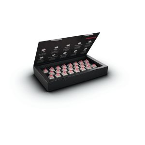
General Information
Barcode Scanners
·
Barcode symbologies
supported by Cherry keyboards
Magnetic Stripe Readers
·
History, dimensions,
data format, AAMVA, etc.
·
How many characters can be
programmed/written on the tracks of an ISO magnetic card?
·
How does the Magnetic Stripe Reader
on Cherry keyboards interface with the PC?
·
How do I clean the Magnetic Card Reader
on my Cherry keyboard?
Miscellaneous
·
What languages does Cherry
offer in its keyboard line?
·
Does Cherry sell a keypad that
will work with laptop computers and NOT affect the NumLock on the laptop?
·
Port/Pin layout 6 pin Mini-DIN
(PS/2) and 5 pin DIN (AT) connectors
·
Stop Character Check
·
On my PC with an MSI motherboard my PS/2
keyboard does not work
·
The PC begins to beep when I press
several keys
·
USB keyboard does not work in MS-DOS
or Safe Mode under Win9x
·
Caps, Num, or Scroll Lock are
automatically switched on (mainly USB systems)
·
How can I display or print out the Euro
symbol using the Cherry keyboard?
·
The Euro symbol only appears in
some of my fonts
·
Does Cherry sell a Serial
converter for the G84-4400 trackball units?
·
ERROR: No Cherry supported devices
found
·
Using a PS/2 to USB adapter
·
All three lights are flashing on
the keyboard
Pointing Devices
·
Replacing a Serial mouse with a
PS/2 mouse: Error message under WinNT4
·
Connecting a PS/2 mouse to the
COM port
Smart Card Readers
·
History,
Introduction, Properties, types of cards, Operating systems, etc.
·
Will Cherry’s smart card
readers work with Military issued CAC cards?
(G83-67xx)
·
After installing smart card
reader the system hangs when shutting down
·
Connecting the keyboard to
two computers using a KVM (change over) switch
·
LED flashes red – Protected PIN
entry mode – PIN does not leave the keyboard
(G83-67xx) –
Under Win2000 or WinXP
·
Deactivation of
subsequently installed MS Smart Card Base Components
Warranty/Repairs
·
Can repair parts be purchased for
Cherry keyboards?
·
Where can I get my Cherry keyboard
repaired in Canada?
·
Where can I get my Cherry keyboard
repaired in the US?
·
How can I tell if my Cherry SPOS,
LPOS, or MPOS keyboard is still under warranty?
·
How can I tell if my Cherry RC series
keyboard is still under warranty?
·
How can I tell if my Cherry G80, G81,
G83, G84 series keyboard is still under warranty?
Programming Information
Barcode Scanner Programming
·
How do I program a carriage return for
my barcode device used with a Cherry PS/2 keyboard?
·
How do I program a carriage return for
my barcode device used with a Cherry 1900/3100 keyboard?
·
How do I disable the Code ID and/or
Modifier (“A”,”E”, or extra “0” in front of the barcode) for my Cherry PS/2 AP
keyboard?
Key Programming
·
How do I disable the Programming key on
my G81-8308 keyboard?
·
How do I set a key back to default on
my PS/2 AP keyboard?
·
How do I program a key on my PS/2 AP
keyboard?
·
How do I program a key on my USB AP-POS
keyboard?
·
NumLock or Caps Lock key turns off
when a card is swiped
Magnetic Stripe Reader
Programming
·
How do I program my Cherry PS/2
keyboard to work with Microsoft RMS?
·
How do I program my Cherry USB keyboard
to work with Microsoft RMS?
·
How do I program my Cherry PS/2
keyboard to work with PC Charge Pro (Payment Server)?
·
How do I program my Cherry USB
keyboard to work with PC Charge Pro (Payment Server)?
·
How do I program my Cherry PS/2
keyboard to work with Microsoft POS?
·
How do I program my Cherry USB
keyboard to work with Microsoft POS?
·
How do I program my Cherry PS/2
keyboard to work with QuickBooks?
·
How do I program my Cherry USB
keyboard to work with QuickBooks?
·
How do I program my Cherry PS/2
keyboard to work with IC Verify?
·
How do I program my Cherry USB
keyboard to work with IC Verify?
Miscellaneous
·
How do I set the entire keyboard back
to factory default?
Barcode
symbologies supported by Cherry keyboards
This article describes:
Supported bar code symbologies
Description:
What bar codes can be read when I attach an undecoded bar code scanner to the
Cherry 7000, 8000, 1900, & 3100 keyboards?
Answer:
Most bar codes can be decoded. The keyboard automatically detects the specific
bar code symbology. A list of all bar codes that can be decoded can be found in
the User Manual.
Supported bar code symbologies:
Code 39
Code 128
Codabar
Interleaved 2/5
Industrial 2/5
MSI
Plessey
Matrix 2/5
Code 93
Code 11
Code 16K
EAN/JAN
UPC
History,
dimensions, data format, AAMVA, etc.
- History
of the Plastic Card
In 1950, the Diners Club issued the first all plastic card for payment.
The use of plastic cards for payment quickly spread due to the low price
of PVC as well as the entry of Visa and MasterCard into the plastic money
arena.
Early plastic cards were embossed with general data such as the card
number and the cardholder's name. Signature fields and security printing
were a feature of these cards created to provide protection against
tampering and forgery. These security features quickly proved faulty as
they relied solely on the retail staff for visual verification. Fraud and
transaction costs increased yearly. The need for security and cost
improvements was deemed essential.
To reduce transaction costs, the magnetic card of today was created. A
magnetic stripe added to the back of these plastic cards enabled data to
be stored in a machine readable form.
- Magnetic
Stripe Card Dimensions

There are two different types of magnetic stripe tape, high energy and low
energy. High energy is a type of magnetic stripe tape made up of tiny
particles that aren't easily altered when in contact with a magnetic
field. It makes the magnetic card less likely to be accidentally erased.
On the other hand, low energy magnetic tapes can be easily erased because
it uses different particles.
- Magnetic
Card Data Format
A track is the encoded information on the magnetic stripe of a plastic
card. Cherry keyboards with an integrated magnetic card reader have the
capability of reading up to 3 tracks in various combinations.
Diagram of 3 Tracks on a Magnetic Stripe Card

Track 1
Per ISO 7813 for financial cards: Track 1 can contain up to 76
alphanumeric data characters (including control characters) with a
recording density of 210 BPI (bits per inch) and a character configuration
of 7 bits per character.
Per AAMVA standards: Track 1 can contain up to 82 alphanumeric data
characters (including control characters) with a recording density of 210
BPI and a character configuration of 7 bits per character.
Track 2
Per ISO 7813 for financial cards: Track 2 can contain up to 40 numeric
data characters (including control characters) with a recording density of
75 BPI and a character configuration of 5 bits per character.
Per AAMVA standards: Track 2 can contain up to 40 numeric data characters
(including control characters) with a recording density of 75 BPI and a
character configuration of 5 bits per character.
Track 3
Per ISO 7813 for financial cards: Track 3 can contain up to 107 numeric
characters (including control characters) with a recording density of 210
BPI and a character configuration of 5 bits per character.
Per AAMVA standards: Track 3 can contain up to 82 alphanumeric characters
(including control characters) with a recording density of 210 BPI and a
character configuration of 5 bits per character.
AAMVA - American Association of Motor Vehicle Administrators; a standard
for reading and encoding driver’s license data on magnetic stripe cards.
- What Kind of Data is on a Credit Card?
Abbreviations:
FC - Format Code, a control character
FS – Field Separator, a control character
SS - Start Sentinel, also known as a header
ES - End Sentinel, also known as a terminator
LRC - Longitudinal Redundancy Check character
Track 1 of a Credit Card
*SS (Header) - optional
*FC (Format code)
*Credit Card Number (maximum of 19 digits)
*FS (field separator) - usually ^
*Cardholder's Name
*FS (field separator) - usually ^
*Expiration Date (YYMM)
*Service Code (maximum of 3 digits)
* Discretionary Data - may include some or all of the following:
*PVKI - PIN Verification Key Indicator
*PVV - PIN Verification Value
*CVV - Card Verification Value
*CVC - Card Verification Code
*ES (terminator) - optional
*LRC (Longitudinal Redundancy Check Character)
Sample of Track 1 Credit Card Data - without header or terminator
B4826762900098714^DOE/JANE S^0009836000000000760000008970000
Track 2 of a Credit Card
*SS (header) - optional
*Credit Card Number
*FS (field separator) - usually =
*Expiration Date (YYMM)
*Discretionary Data
*ES (terminator) - optional
*LRC (Longitudinal Redundancy Check)
Sample of Track 2 Credit Card Data - without header or terminator
4826762900098714=09836000076000897000
- Magnetic
Card Readers - Cherry Specific Information
Cherry uses Mag-Tek brand magnetic card readers in our keyboards.
Information on Mag-Tek can be found on their website www.magtek.com.
The magnetic card reader is invisible to the keyboard and the PC until a
card is swiped (read). When a card is read, the magnetic card reader takes
over the keyboard interface to the PC and sends card data using the same
scan codes used by the keyboard. The PC cannot distinguish between data
from the keyboard and data from the magnetic card reader.
The magnetic card reader is being supplied with power by the PC.
Cherry keyboards can read both high energy and low energy cards
(coercivity).
Cherry keyboards can read any credit card that is compliant with the
following ISO standards:
ISO 7810 - Physical Characteristics of Credit Card Size Document
ISO 7811-2 - Magnetic Stripe
ISO 7811-4 - Location of Tracks 1 & 2
ISO 7811-5 - Location of Track 3
ISO 7813 - Financial Transaction Card Data
In the near future, all Cherry 3 track keyboards will be able to read
AAMVA cards. Currently, any 7000/8000 or 1950 three track keyboard has the
ability to read AAMVA cards with a firmware change that can be downloaded
at the customer site.
- 6. What is AAMVA
and What Kind of Data is on an AAMVA Card?
AAMVA - American Association of Motor Vehicle Administrators; a standard
for reading and encoding driver’s license data on magnetic stripe cards.
Track 1 data
The following data is on track 1 AAMVA cards in order as follows:
*State or Province
*City
*Name
*Address
Track 2 data
The following data is on track 2 AAMVA cards in order as follows:
*ISO Issuer Identifier Number (IIN)
*Drivers License / Identification Number
*= (field separator)
*Expiration Date
*Birth data
*DL/ID# overflow
Track 3 data
The following data is on track 3 AAMVA cards in order as follows:
*Template V#
*Security V#
*Postal Code
*Class
*Restrictions
*Endorsements
*Sex
*Height
*Weight
*Hair Color
*Eye Color
*ID#
*Reserved Space
*Error Correction
*Security
How
many characters can be programmed/written on the tracks of an ISO magnetic
card?
This article refers to:
All Cherry magnetic card keyboards
Description:
The ISO-compliant coding of magnetic cards is as follows:
Track 1: 79 characters (incl. start, stop, LRC), each with 7 bits per character
(6 Bit + Parity bit) at 210 bits per inch.
Track 2: 40 characters (incl. start, stop, LRC), each with 5 bits per character
(4 Bit + Parity bit) at 75 bits per inch.
Track 3: 137 characters (incl. start, stop, LRC), each with 5 bits per
character (4 Bit + Parity bit) at 210 bits per inch.
How
does the magnetic stripe reader on Cherry keyboards interface with the Pc?
This article refers to:
All Cherry magnetic card keyboards
Description:
The CHERRY magnetic card reader keyboards can only read
magnetic cards. How and where the data are written to the magnetic card depends
only on the recording device and the application of the magnetic card.
CHERRY is therefore unable to supply information about where, for example, the
customer number can be found / deciphered on a card with magnetic strips. This
type of information can be obtained from the place where your magnetic cards
are written or from your application software supplier.
CHERRY magnetic cards read the card contents one by one via the keyboard
interface, i.e. the card data are sent to the PC system track by track,
character by character, as though the card data had just been entered manually.
Processing of the data in your application codes is therefore
driver-independent. The data can be processed by the application program as
pure keyboard entry strings.
However, to distinguish between card data and genuine keyboard entries, the
CHERRY magnetic card keyboards provide "headers" and
"terminators" (see Knowledge Base for Headers and Terminators).
How do
I clean the magnetic card reader on my Cherry keyboard?
This Article refers to:
All Cherry Keyboards with Integrated Magnetic Card Readers
Description:
How do I clean the Magnetic Card Reader on my Cherry Keyboard? Does Cherry
offer any cleaning kits?
Solution:
It is recommended that you use a card cleaning kit designed to clean magnetic
card readers. This will insure that no damage is done to the heads. Cherry does
not sell card cleaning kits. In the US, we recommend the following companies:
Clean Team
phone: 800-888-8830
url: http://www.cleanteam.com
KIC Products
phone: 800-818-1932
url: http://www.kicproducts.com
What
languages does Cherry offer in its keyboard line?
Language Options for Cherry Keyboards
***Cherry has manufactured keyboards in a
variety of different languages. Listed below are languages that we have done in
the past over our entire keyboard product line. Please note that not all
languages are available for all keyboard models. Please contact Cherry Sales
for specific information.
AE = UK/ARABIC
AR = US/ARABIC
BB = BULGARIAN/US/CYRILLIC ("L" SHAPED ENTER KEY)
BE = BELGIUM
BG = BULGARIAN (US/CYRILLIC)
CD = CANADA
CH = SWITZERLAND
DE = GERMAN
DK = DENMARK
EE = ESTONIA
ES = SPAINIS
FA = FRENCH/ARABIC
FR = FRENCH
GB = UK/ENGLISH
GR = GREECE
HU = HUNGARY
IL = US/HEBREW
IS = ICELAND
IT = ITALY
JA = JAPAN (HIRAGANA)
JK = JAPAN (KATAKANA)
KO = US/KOREAN
KR = UK/KOREAN
LA = LATIN AMERICAN
LT = US/LITHUANIAN
NL = NETHERLANDS
NO = NORWAY
PL = POLAND
PO = PORTUGAL
RA = UK/CYRILLIC
RB = US/CYRILLIC
RC = US/CHINESE
RD = GERMAN/CYRILLIC
RE = US/PERSIAN
RF = GERMAN/PERSIAN
RG = US/CYRILLIC ("L" SHAPED ENTER KEY)
RL = US/CYRILLIC/LITHUANIAN
RO = ROMANIA
SF = SWEDEN/FINLAND
SK = SLOVAKIA
SL = SLOVENIA/CROATIA (LATIN I)
TF = TURKEY (LAYOUT F)
TH = US/THAILAND
TQ = TURKEY (LAYOUT Q)
TS = CZECH REPUBLIC
US = US/ENGLISH
YU = YUGOSLAVIA
Does
Cherry sell a keypad that will work with laptop computers and NOT affect the
NumLock on the laptop?
Cherry offers 3 styles of numeric keypads:
G80-3700LQAXX0
G84-4700PPBXX
G84-4700PRBXX
**The "XX" varies depending on the language of the keyboard.
The keypads will operate with a notebook computer without affecting the Num
Lock on the Notebook in mode 2. You can put the keypad in mode 2 by:
Using the keypad:
Hold down the "NumLock" and "2" keys and press
"Enter".
Port/Pin
layout 6 pin Mini-DIN (PS/2) and 5 pin DIN (AT) connectors
This article describes:
Differences between Mini-DIN and 5-pole DIN plug
Description:
What's the difference in Mini-DIN (PS/2) and 5-pole DIN (AT) connectors? Does
Cherry supply an adapter cable to change my Mini-DIN / DIN cable to DIN /
Mini-DIN?
Answer:
AT uses a large round 5 pin 'DIN' plug. PS/2 uses a small round 6 pin 'DIN'
plug. Both have the same electrical signals connected. Although you cannot
directly plug into the other for obvious reason, using a small adapter can
change one plug into the other.
You can get the adapters from Cherry using the following part number:
PS/2 -> AT: 617-0848
AT -> PS/2: 617-0580
Pin layout
|
|
Mini DIN
|
Color
|
DIN Plug
|
|
DATA
|
1
|
White
|
2
|
|
FREE
|
2
|
|
3
|
|
GRND
|
3
|
Black
|
4
|
|
+5V
|
4
|
Green
|
5
|
|
CLOCK
|
5
|
Yellow
|
1
|
|
FREE
|
6
|
|
|
|
DIN
|
Mini DIN
|
|

|

|
Stop
Character check
This article refers to:
- Cherry POS keyboards with barcode and/or magnetic card reader
- Cherry Tools Software for POS keyboards
Description:
Programming the keyboard using the Cherry Tools Software: If you deactivate the
option 'Stop Character Check Enabled' you will apparently receive a random
start character for different magnetic cards or barcodes.
With the first card (or bar code) you receive a dash (-), with the second one a
slash (/), third an exclamation mark (!), fourth a character P, etc...
This 'random characters' problem can be fixed by activating the option 'Stop
Character Check Enabled' again.
What causes this behavior?
Solution:
The Start Character is always the ´%´ character. It is not programmable and it
will not be included in the output data of your CHERRY keyboard since it does
not belong to the 'real' data of the track.
Disabling the 'Stop Character Check' the LRC character (the ´check-sum´) could
be interpreted as a start character.
The LRC character will always be different depending on the preceding
characters.
On my
PC with an MSI motherboard my PS/2 keyboard does not work
This article refers to:
all keyboards with PS/2 connector
at use on PCs with MSI Motherboard
On my PC with a MSI Motherboard the Keyboard does not work on the PS/2 port.
Why? Affected Motherboards are:
- MSI KT266 PRO2
- MSI 845 Ultra ARU
Answer:
According to MSI you have to update the latest Bios version. You can find more
information at http://www.msi.com.tw (direct link to the Bios-page:
http://www.msi.com.tw/support/bios/note.htm!)
If there’s no bug fix available please try following workaround: In
"Advanced Bios Feature Setup" you have to set the option "Num
Lock" to "OFF". Then the keyboard should be recognized.
The
PC begins to beep when I press several keys
This article refers to:
All keyboards
Symptom:
When I press several keys the PC begins to "beep". This especially
appears while playing games.
Reason:
This symptom is called "Ghost Key". Ghost Keys can appear when more
than two keys are pressed simultaneously. There are some specified
key-combinations that have to be detected by the keyboard electronic (e.g.
Ctrl+Alt+Del). Not specified combinations can be recognized but it’s not a
must. This just depends on the layout of a keyboard.
You can find an overview about the Microsoft specified key combination under:
http://www.microsoft.com/HWDEV/TECH/input/Scancode.asp#New
USB
keyboard does not work in MS-DOS or Safe Mode under Win9x
This article refers to:
MS-DOS
Microsoft Windows 95
Microsoft Windows 98
Description:
If the computer is started in protected mode (e.g. by keeping the [Ctrl] key
pressed or using system configuration tools), it may be that the Cherry USB
keyboard does not respond to any entry. In addition to that you might receive
following (or similar) message:
"Windows mouse support: Windows could not find a mouse on your computer.
You can now connect a serial mouse. When connecting a PS/2 mouse to the
computer you must first switch the computer off."
Solution:
Win95 and Win98 does not load USB drivers in protected mode. Also MS-DOS does
not load a special USB driver.
This is the intention - protected mode is there precisely to prevent any
drivers being loaded.
In order for you to use your CHERRY USB keyboard, you should activate the USB
support via the BIOS of your PC (also called 'legacy mode'). This should be a
setting option of the BIOS.
Caps,
Num, or Scroll Lock are automatically switched on (mainly USB systems)
This article refers to:
Microsoft Windows 98
Various BIOS versions
Usually USB technology
Description:
After my computer has powered up, Caps Lock mode is switched on automatically
(including Num Lock and Scroll Lock)
Solution: Please be informed about following FAQ Q247853 - CAPS LOCK Key Is on at Startup With Universal Serial
Bus Keyboard Installed at Microsoft!
Additional information:
A keyboard is not responsible for "Caps, Num and Scroll Lock".
IBM-compatible keyboards only send the "key position code" to the PC,
together with information on whether the key was pressed or released.
The keyboard driver of the operating system or the BIOS makes
"legible" characters from these key position codes (providing no
operating system has been loaded).
In the case of the "Caps Lock" key, for example, this means that, in
simple terms, keyboards only send the "number" of the "Caps
Lock" key to the system if the key has been activated.
The system then establishes that this key was the "Caps Lock" key,
and switches the "Caps Lock" mode in the system.
As you did not constantly press the "Caps Lock" key immediately after
the computer was powered up, the system itself must switch on "Caps
Lock" mode.
You should therefore test the following in order to narrow down the nature of
the problem:
1.
If
this behavior occurs before the operating system has loaded, you should consult
the BIOS manufacturer (a new update may be required). It may be, however, that
the option "Activate Num, Shift or Scroll Lock automatically after
booting" is set in your BIOS. Switch this option off as necessary.
2.
If
this behavior does not occur until after the operating system has loaded, you
should consult your operating system manufacturer (if necessary, request the
fault clearing program 'bug fix' via the Internet).
It is our understanding that Case 2 occurs more frequently (particularly
under WIN 98 / USB systems).
A keyboard error can almost certainly be ruled out in this case.
How
can I display or print out the Euro symbol using the Cherry keyboard?
This article refers to:
All operating systems
Description:
The Euro symbol has not yet been printed on older keyboards. How can I use the
keyboard to produce the Euro symbol?
Solution:
Creating and printing of the Euro symbol is done by your operating system. It
is responsible for creating the Euro symbol. The keyboard electronics has not
changed since the Euro symbol was introduced. The Euro symbol has only been
printed on the new keyboards, but you can still use the keyboard to produce
this character.
With or without the printed inscription: you only need to know how your
operating system generates the Euro symbol.
For European keyboards and Microsoft operating systems, the Euro symbol can be
created by using the key combination "Ctrl" + "e" or
"Ctrl" + "Alt" + "e". For UK Layout keyboards,
use 'ALT GR' and the number '4' key.
The only precondition is an operating system upgrade for printing the Euro
symbol (adds the Euro symbol to your font types, for example).
This program upgrade is already included in Microsoft WIN 98.
For WIN 95 users, Microsoft provides the corresponding upgrade under
http://www.microsoft.com.
Here you will also find information on Euro upgrades to other Windows versions.
Users of other operating systems should contact the relevant manufacturer!
Cherry does not supply Euro upgrades of the OS.
For more information (for Windows operating systems) also go to http://www.microsoft.com/typography/faq/faq12.htm
The
Euro symbol only appears in some of my fonts
This article refers to:
All operating systems
Description:
Although I have already installed my operating system manufacturer's Euro
symbol upgrade, the character does not appear in some of my fonts.
Solution:
Creating and printing of the Euro symbol is done by your operating system. The
electronics of the keyboard has not changed since the Euro symbol was
introduced. The Euro symbol has only been printed on the new keyboards.
Even if you have installed your operating system manufacturer's Euro symbol
upgrade, the Euro symbol can only be added to the fonts of that particular
manufacturer.
So, for example, if you have received other fonts by freeware or via other
application programs, you must also contact the manufacturers of those fonts to
add the Euro symbol.
If this is not possible, then the only remaining option is to look for an
alternative character set with the Euro symbol (e.g. via the Internet or a
specialist dealer).
For more information (for Windows operating systems) also go to http://www.microsoft.com/typography/faq/faq12.htm
Does
Cherry sell a serial converter for the G84-4400 trackball units?
Serial Converters For the G84-4400
Trackball Unit
Keyboard- Converter P/N
G84-4400PPBXX- 0007-2101
G84-4400PRBXX- 0007-2101
G84-4400PPAXX- 0007-1813
G84-4400PRAXX- 0007-1813
**The "XX" varies depending on language of keyboard
Please call the keyboard hotline for further details
Europe: (49) 9643 18-206
United States: 800-510-1689
Error:
No Cherry supported devices found
This article refers to:
Cherry Tools version 4.0 and higher
Description:
KeyMan error: “No Cherry Supported Devices found” occurs
every time the computer is booted.
Solution:
This error message appears if you install a newer version of
Cherry Tools without rebooting the computer after uninstalling the older
version.
- Do a complete uninstall of the Cherry Tools software by
going to Start->Programs->Cherry Tools->Setup. Choose
to remove the installation and then choose to remove the complete package.
- Reboot the computer.
3. Install the new version of Cherry Tools
Using
a PS/2 to USB adapter
This article refers to:
All Cherry PS/2 keyboards
Description:
Using a PS/2 to USB adapter to convert a Cherry PS/2
keyboard to a USB interface
Solution:
Not all adapters work properly. Some adapters may work with
some keyboard models but not others. Some adapters may work with come computer
models and not others.
Cherry has found during testing that “cable” type adapters
have a better chance of working than the “stub” type adapter.
Because of these
inconsistencies, Cherry does not recommend nor support the use of PS/2 to USB
adapters. We strongly recommend that you purchase a USB keyboard.
All
Lights are Flashing on the Keyboard
This article refers to:
All Cherry keyboards
Description:
All lights are continuously flashing on the keyboard
Solution:
An internal electronic error will cause all lights on the
keyboard to continuously blink. This error could be caused by spilling liquids
into the keyboard or by a fault in the keyboards logic board.
Please contact Cherry Keyboard Technical support to check on
warranty status and for the nearest authorized repair center.
1-800-510-1689 or keyboardsupport@cherrycorp.com
Replacing
a serial mouse with a PS/2 mouse: Error message under WinNT4
This article
refers to:
Microsoft Windows NT 4.0
Description:
A serial mouse was connected to my Windows NT 4.0 computer. I have changed it
for a PS/2 mouse. The PS/2 mouse is duly recognized by the operating system.
When the machine is restarted, however, the error message "A Service Could
Not Be Started ....see Event Protocol" is displayed. How can I get around
this message?
Solution:
This message is generated by the driver of the serial mouse. To switch this
driver off, select the icon "Devices" under START - SETTINGS - SYSTEM
CONTROL. Then search for the entry "Sermouse" and click on the button
"Start Type". Now select "deactivated" from the list which
appears, and click on "OK". Then "Close" and restart the
system. The error message should not appear again.
Connecting
a PS/2 mouse to the COM port
This article
refers to:
MS Windows operating systems
Description:
I want to connect my PS/2 mouse to my PC's COM port. I have bought an adapter
cable for this purpose and connected the mouse, but the mouse wasn't recognized
- not even after various BIOS adjustments!
Solution:
Not every PS/2 mouse works with a COM port adapter. Use a "COMBO"
mouse. It supports both protocols.
History, Introduction, Properties, Types of cards, Operating
Systems, etc.
- History
of the Plastic Card
In 1950, the Diners Club issued the first all plastic card for payment.
The use of plastic cards for payment quickly spread due to the low price
of PVC as well as the entry of Visa and MasterCard into the plastic money
arena.
Early plastic cards were embossed with general data such as the card
number and the cardholder's name. Signature fields and security printing
were a feature of these cards created to provide protection against
tampering and forgery. These security features quickly proved faulty as
they relied solely on the retail staff for visual verification. Fraud and
transaction costs increased yearly. The need for security and cost
improvements was deemed essential.
To reduce transaction costs, the magnetic card of today was created. A
magnetic stripe added to the back of these plastic cards enabled data to
be stored in a machine readable form. However, it was quickly learned that
this data was still vulnerable. It can be read, deleted, and re-written by
anyone with the right device. In order for the retailers to protect
themselves against fraud, they had to go on-line with the card issuer for
approval at the time of sale. This brought transaction costs back up, and
still didn't eliminate the need for the retail staff to visually verify
signatures. Security is still a major issue. With the increase in
technology, off-line transactions are necessary. The need for the Smart
Card was eminent.
- Introduction
of the Smart Card
1968 Jürgen Dethloff and Helmut Grötrupp, two German inventors, applied
for a patent on their idea of incorporating an integrated circuit with a
plastic card.
1970 Kunitaka Arimura, a Japanese inventor, filed the first patent for the
Smart Card of today.
1974 Roland Moréno of France began obtaining patents on several functional
aspects of the Smart Card and began selling licenses to manufactures.
1984 The French Postal and Telecommunications services successfully
carried out a field trial with telephone cards.
1984/85 Germany implemented a pilot project for telephone cards using
magnetic stripe, holographic, and smart cards. Smart Cards were proved to
have the best security, flexibility, and reliability of the three
technologies.
1990 Over 60 million French telephone Smart Cards were in circulation.
1993 The German Social Security Authority and the Sickness Fund Doctors
Association began issuing a Health Card to every German citizen (approx.
79 million).
1.
What is a Smart Card?
A Smart Card is a plastic card with an electronic microchip embedded in it. It
is the size of a conventional credit card.
Physical Properties

ISO 7810 (ID-1 Card Standard)
Dimensions - 85.6 mm x 54 mm
Corner radius - 3.18 mm
Card thickness - .76 mm
ISO 7816-2 (Contact Placement Standard)
Dimensions noted in diagram
Electrical Properties


Most Smart Cards have eight contact fields. These form the electrical interface
between the reader and the card's microprocessor. Because contacts C4 and C8
are reserved for future use, some manufacturers have issued a 6 contact Smart
Card for cost savings. Currently, these are functionally the same.
A Smart Card requires a supply voltage of 5volts +/- 10%. There currently is a
push for Smart Card standards to support 3volt technology because of the
increase of Smart Card applications in telecommunications such as mobile
phones. A wider voltage range handling 3-5 Volts will more than likely become
mandatory in the future.
- Types
of Cards - Contact & Contactless

Contact Cards
A contact Smart Card consists of the plastic card body, electrical
terminal (the gold plated contacts), and a chip. In order to transfer data
to and from the contact Smart Card, it must be inserted into a Smart Card
reader.

Contactless Cards
A contactless Smart Card consists of two plastic card bodies, a chip, and
an antenna. Data can be transferred to and from the contactless card with
the antenna and a coupler unit; without any physical contact.
There are two types of contact cards. Memory Cards and Microprocessor
Cards. Memory cards are sometimes referred to as Smart Cards, but a
Microprocessor Card is a true Smart Card.
- Microprocessor
Cards (Smart Cards)
A Smart Card contains a CPU, RAM, EEPROM, and ROM (its own operating
system). A Smart Card is a "computer on a chip". This
"computer on a chip" allows for transmission, storage and
processing of data with high security. The Smart Card's operating and
security logic systems supervise data transmission over the serial
interface. These memory functions of writing, erasing, and reading are
controlled.
ROM - Read Only Memory; this type of memory can only be written to once
during production. A Smart Card's ROM contains most of the operating
system, as well as diagnostic and testing functions. The ROM creates the
"secure operating system" for Smart Cards. It eliminates back
doors and other system tampering by programmers.
EEPROM - Electrical Erasable Programmable Read Only Memory; this type of
memory is used in Smart Cards for all data and programs that need to be
modified or erased. EEPROM functions like a hard disk in a PC. The data
will remain in memory even when there is no power.
RAM - Random Access Memory; this is the Smart Card's memory during one
session. As soon as power is lost, the RAM will be cleared of all data.
CPU - Central Processing Unit; this is the device in the Smart Card that
interprets and executes instructions. It is the "brain".
Smart Card Operating System
A Smart Card's operating system usually contains between 3 and 24 Kbytes
of code depending on the application(s) the card is used with. Unlike the
operating systems you are used to such as Windows, the Smart Card OS
doesn't contain a user interface. There is no access to external
peripheral or storage media. The OS is responsible for:
*File management
*Memory management
*Instruction programming and execution control
*Protected access to data
*Loading, operating, and management of applications
*Data transmission
*Execution and management of cryptographic algorithms.
Asynchronous Data Transmission
All communication to and from the Smart Card and the reader, is carried
out over the C7 contact. Earlier, we defined the C7 contact as the Input /
Output contact. Because data can only go over this one contact, communication
is termed "half-duplex". This simply means that only one party
can communicate at a time, either the terminal (reader) or the Smart Card.
Communication is always initiated by the terminal, the card only responds
to the terminal's instructions. The card never transmits data without a
request from the terminal first. This simulates a client - server
relationship. The Smart Card is the client, and the server is the
terminal.
Communication Flow of Card and Terminal
Step 1 - Smart Card is inserted into the reader
Step 2 - The Smart Card's contacts are electrically activated
Step 3 - The Smart Card executes a power-on-reset and sends an
answer-to-reset (ATR) to the terminal
Step 4 - The terminal evaluates the ATR and pinpoints different card parameters.
At this point, depending on the card, the terminal may send a PTS
instruction to the card. PTS is protocol type selection. This instruction
is used by the terminal to set various transmission parameters relating to
the card's protocol. We will go over protocols in the next section.
Step 5 - If the PTS instruction was sent to the Smart Card, the Smart Card
responds with an answer.
Step 6 - Half duplex communication continues. The terminal sends an
instruction, the Smart Card then sends an answer. This process continues
until the card is deactivated (taken out of the reader).
Communication between a Smart Card and the terminal is serial. This means
that all the data processed is converted to a bit-serial data stream. (One
byte is separated into eight individual bits. These bits are sent down the
data stream one after another). In Smart Cards, data transmission is
asynchronous. This means that each byte (8 bits) must be provided with
additional bits. One of the additional bits is called a start bit. The
start bit signals the beginning of a sending sequence (it tells the
receiver that the byte is coming). After the byte, there is a parity bit
for error detection and one or two stop bits. The stop bits give the
receiver and the sender time to prepare for the next byte. An advantage of
asynchronous transmission is that it doesn't require a clock. The timing
is generated by the timing between bits rather than a clock.
- Transmission
Protocols
A protocol is a set of rules and procedures governing the interchange of
information between a Smart Card and the terminal. The protocol is the
entire structure of communication.
|
Protocol
|
Description
|
|
T = 0
|
Asynchronous, half-duplex, byte
oriented
|
|
T = 1
|
Asynchronous, half-duplex, block
oriented
|
|
T = 2
|
Asynchronous, full-duplex, block
oriented
|
|
T = 3
|
Full duplex, currently not used
|
|
T = 4
|
Asynchronous, half-duplex, byte
oriented (expansion of T=0)
|
|
T = 14
|
For national functions
|
|
|
|
Protocols T=0, and T=1 are the most commonly
used protocols world wide. Protocols T=5 through T=13 and T=15 are reserved for
future use and functions. T=14 is currently used in Germany in their card
phones.
Transmission Protocol T=0
The smallest unit processed by the T=0 protocol is a single byte. This coins
the term "byte-oriented". Because of this protocol's byte
orientation, if a transmission error is detected, the byte must be requested
again. Detection of these errors is possible because each byte has a parity bit
attached. It is easier to understand how each byte is transmitted with the T=0
protocol with the following diagram:

The guard time bit's main function is to separate individual bytes during
transmission. This gives the sender and the receiver more time to carry out the
transmission protocol's functions. If an error is detected during this byte
transmission, the guard time bit turns into an error message that tells the
card to resend the byte to the reader.
Transmission Protocol T=1
The T=1 protocol is a block protocol. The block is the smallest data unit that
can be transmitted between the card and the terminal. Blocks are groups of
bytes.
There are three types of blocks:
*Information Blocks (I-Blocks) - they are used for transparent exchange of
application layer data.
*Reception Acknowledgment Block (R-Block) - never contains an information
field, it serves for reception confirmation.
*System Blocks (S-Block) - used for control data which relate to the protocol
itself.
T=1 transmission block structure

Blocks consist of a prologue field, information field, and epilogue field. The
prologue and epilogue fields are mandatory.
Prologue field - transmitted at the beginning of a block; consists of the NAD,
PCB, and LEN
*NAD - Node address - contains the blocks target and source addresses
*PCB - Protocol Control Byte - controls and supervises the transmission
protocol
*LEN - Length - indicates the length of the information field in hexadecimal
form
Information field - in an I-Block a container for the application layer's data.
The contents of this field are transmitted transparently. This means simply
that this information is forwarded by the transmission protocol without
analysis or evaluation. Information field in an S-Block: a container for the
transmission of data.
*APDU - Application Protocol Data Unit, command ADPU - represent instructions
to the card, response ADPU - answers from the card
Epilogue field - transmitted at the end of a block; contains error detection
code (EDC)
- Memory
Cards
A memory card contains a memory chip with read/write capability and in
some cases, hardwired security functions. Memory cards are less expensive
than microprocessor (Smart) cards, but they are also less functional. They
contain limited address and security logic, EEPROM and ROM memory. The ROM
is fixed, and the EEPROM is write/erase and read at will. In simple card
designs, the logic exists to prevent writing and erasing of data. More
complex card designs allow for restricted access of reading the memory. An
example of a memory card application is a pre-paid telephone card.
- Synchronous
Data Transmission
Synchronous transmission is a serial transmission that requires a clock
signal to provide timing and check the output of the data. It was designed
with great simplicity. Synchronous transmission in memory cards allow the
application in the terminal to access the chip's memory addresses
directly. Little logic is needed in the memory card (which makes them less
expensive). The terminal completely takes over the physical addressing of
memory. The card itself can only block certain areas against erasing.
Transmission protocols used for memory cards are S=8, S=9, S=10
- Smart Card
Readers
A Smart Card reader is also referred to in the industry as an IFD
(interface device), CAD (chip-accepting device), Smart Card adapter, or a
CCR (chip-card reader). Smart Cards themselves are very similar in their
technical construction unlike readers.
Readers can be stationary, remote, work off-line, on-line, be battery
powered or get its power supply from a connecting system. We are going to
focus on stationary readers that receive their power from a system, mainly
a pc. Throughout this section, we have referred to a terminal. To clarify,
a Smart Card terminal consists of two components; a card reader and a
computer system. The reader only takes care of a mechanical function. The
computer system will control the reader electrically, establish a
connection with other systems, and provide an interface for
administration.
Mechanical Features of Smart Card Readers
In order for a Smart Card to interface with a terminal, you must make a type of
contact that can transmit information electronically. When you insert a card
into a reader, the card's contacts connect to a conductor to the terminal's
computer. This contact to contact interface is necessary for communication.
Reader Contacts
There are two different types of contacting units in readers. Landing and
sliding. Sliding contacts are comprised of a spring based unit that drags the
contact elements across part of the Smart Card and it's contact fields to make
connection. While sliding contacts in readers make for a less expensive reader,
it has a major draw back. Sliding can leave scratch marks on a Smart Card and
slowly wears down the card's gold plated surface. Mechanical landing contacts
on the other hand use a lever type mechanism. Inserting the card causes the
contact unit to press against the contact fields versus scraping across them.
This greatly extends the life of the Smart Card and the reader.
Cherry Specific Hardware Information
Cherry currently uses three different chip sets or readers that are integrated
into our keyboards. They include Gemcore, G&D, and Cherry's own chipset.
All of our integrated readers feature mechanical landing contacts except for
our G83-6700 keyboard which has sliding contacts as a standard option. (Landing
contacts are available at an extra cost).


Will
Cherry’s smart card readers work with Military issued CAC cards?
This article refers to:
All Cherry Smart Card Readers
Answer:
All Cherry Smart Card Readers will work with Military issued
CAC cards.
The following models have been CAC Certified:
G83-6644 Smart Card Keyboard
G83-6744 Smart Card Keyboard
ST-1044 Stand Alone Smart Card Reader
SR-4044 PCMCIA Smart Card Reader
After
installing smart card reader system hangs when shutting down
This article refers to:
Cherry SmartBoard, G83-67xx
using HBCI Setup up to version 1.1 respectively
Smart Card Keyboard Driver up to version 1.6
under
Microsoft Windows 98
Microsoft Windows ME
Description:
After installing the chip card reader the system hangs while shutting down or
the time until the PC switches off is longer than before.
Solution:
Uninstall the HBCI Setup up to version 1.1 respectively Smart Card Keyboard
Driver up to version 1.6.
Reboot your system.
Use Cherry Setup for SmartCard Keyboard, version 2.0 or higher!
Please note:
Under http://support.cherry.de -> "personal Login" -> Change
Profile -> Next -> "Keyboards according to PC/SC specification"
you can subscribe the appropriate newsletter. It will inform you about data and
features/bug fixes of new Setup versions!
Connecting
the keyboard to two computers using a KVM (change over) switch
Description:
Cherry keyboards with PC/SC compatible smart card reader (e.g. G83-6744,
G83-6644, etc.) are to be used simultaneously at two computers. For this a
mechanical or electronic change-over switch is used, which switches the
keyboard depending upon requirement to the first or the second PC.
Accessing the smart card reader is not possible over the change-over switch.
But: The keyboard directly plugged to the PC works fine.
Using an electronic change-over switch 'blocks' the special commands for
communication with the smart card reader.
Using a mechanical change-over switch the smart card reader will be
deactivated.
Solution:
The Cherry keyboard's chip card reader is compatible with the 'PC/SC' standard
initiated by Microsoft. A PC/SC reader is no longer addressable after the
source voltage has been switched off or over.
The PC/SC Resource Manager saves the last 'communication status' of the chip
card reader. The reader executes a reset after the operating voltage is
applied. It is then addressable. It does not set itself to 'active'
('claimed'), however, but has to be 'restarted' ('reclaimed') again by the
driver.
This procedure is the conversion of the PC/SC specification. In a different
procedure, the status of the reader would no longer be defined precisely to the
Resource Manager.
This behavior could be solved only using a mechanical change-over switch and
switch only data and clock control - but not the power supply.
LED
flashed red – Protected PIN entry mode – PIN does not leave the keyboard
This article refers to following CHERRY keyboards with
CHERRY PC/SC smart card readers (and the feature 'Protected PIN Entry Mode'):
Description:
In Protected PIN Entry Mode the verification of the correct PIN takes place
within the keyboard, i.e. the PIN will not be transmitted to the PC, but
transmitted within the keyboard directly to the smart card.
Thus it is not possible to spy the PIN from the data line of the keyboard wire
or with a 'Trojan' program on the PC.
As a visible display for the activation of the "Protected PIN entry
mode" the PIN-LED (Scroll LOCK) flashes red.
The Protected PIN entry mode can be activated by standard CT-API commands
'Perform verification' or 'Modify verification DATA'.
The specification is called MKT version 1.0 and can be downloaded under
http://www.teletrust.de --> publications --> MKT. The security of this
solution was evaluated for some versions of the keyboards by TUEV IT with the
approval IT SEC E2-high (due to German signature law).
Deactivation
of subsequently installed MS Smart Card Base Components
This article refers to:
a) Cherry keyboards 'SmartBoard G83-67xx' and
b) subsequently installed 'MS Smart Card Base Components'
under
MS Windows 2000
MS windows XP
Description:
The MS Smart Card Base Components (necessary for the operation of PC/SC based
smart card readers) are already part of the Win2000 and WinXP operating system.
These components are only available for Win9x, WinME, and WinNT.
Installing them under Win2000 or WinXP destroys already available functions and
thus the system can not access the PC/SC smart card reader any more.
Uninstallation of the 'Microsoft Smart Card Base Components' will not fix the
system!
To deactivate the components and reestablish the origin functions of the
operating system refer to following solution:
Solution for Win2000:
1) Login as an Administrator
2) Under START - Execute successively type in following commands:
Regsvr32 %windir%\system32\scardssp.dll
[confirm with OK]
Scardsvr reinstall
[confirm with OK]
3) Have a look in Start - Settings - Control Panel - Administrative Tools -
Services and locate the entry 'Smart Card'. Check the current status. If it
should not be started, try to start it (right mouse button - 'start')
4) Independent whether the service can be started or not set the type of start
from 'manual' to 'automatic'.
5) Restart your computer.
Solution for WinXP:
1) Login as an Administrator
2) Under START - Execute successively type in following commands:
Regsvr32 %windir%\system32\scardssp.dll
[confirm with OK]
Scardsvr reinstall
[confirm with OK]
3) Create a reg file (name does not matter, e.g. 'active.reg') with the
following content (please absolutely pay attention for the correct spelling!):
Windows Registry Editor Version 5.00
[HKEY_LOCAL_MACHINE\SYSTEM\CurrentControlSet\Services\SCardSvr]
"ObjectName"="NT AUTHORITY\\LocalService"
[HKEY_LOCAL_MACHINE\SYSTEM\CurrentControlSet\Services\SCardDrv]
"ObjectName"="NT AUTHORITY\\LocalService"
4) Save this file to disk and then double click on it. Thus the registry will
be updated.
5) Have a look in Start - Settings - Control Panel - Administrative Tools -
Services and locate the entry 'Smart Card'. Check the current status. If it
should not be started, try to start it (right mouse button - 'start')
6) Independent whether the service can be started or not set the type of start
from 'manual' to 'automatic'.
7) Restart your computer.
Can
repair parts be purchased for Cherry keyboards?
This article refers to:
All Cherry Keyboards
Answer:
We are sorry but Cherry does not sell repair parts for our
keyboards. The keyboard must be sent to our authorized repair facility to be
repaired.
Cherry does not sell repair parts in order to maintain the
integrity of the repairs and the Cherry quality standards. If repairs have been
completed by an entity other than our authorized service provider, Cherry
cannot guarantee the quality and workmanship that is synonymous with the Cherry
name.
For information on our authorized service provider please
contact Keyboard Technical Support at:
1-800-510-1689 or keyboardsupport@cherrycorp.com
Where
can I get my Cherry keyboard repaired in Canada?
Answer:
Please contact Keyboard Technical Support first to see if
the keyboard is actually in need of repair or if it is a simple fix.
Keyboard Technical Support:
1-800-510-1689 or keyboardsupport@cherrycorp.com
Cherry’s authorized service provider for Canada is Grand Tech Services.
Grand Tech Services
1-800-567-0586
70 East Beaver Creek Rd.
#21-23
Richmond Hill, Ontario
L4B 3B2
Where
can I get my Cherry keyboard repaired in the US?
Answer:
Please contact Keyboard Technical Support first to see if
the keyboard is actually in need of repair or if it is a simple fix.
Keyboard Technical Support:
1-800-510-1689 or keyboardsupport@cherrycorp.com
Cherry’s authorized service provider for the US is Gremark Technologies.
Gremark Technologies
630-705-0900
1400 Brook Drive
Downer’s Grove Ill 60515
www.gtiservice.com
How
can I tell if my Cherry SPOS, LPOS, or MPOS keyboard is still under warranty?
CHERRY WARRANTY INFORMATION
FOR POS SERIES KEYBOARDS
Cherry keyboard / input device warranty time frame:
- The warranty on Cherry SPOS, LPOS, and MPOS series Keyboards is 3
years from date of manufacture for ALL part numbers.
Cherry SPOS series
keyboards are covered by warranty provided:
·
The date code
falls into the correct time frame designated by Cherry. The last five digits of
the serial number are the date code. This can be found on the bottom of the
keyboard. They will consist of four numbers and a letter. The first three
numbers correspond to the day of the year the keyboard was manufactured. The
fourth numbers corresponds to the year in which it was manufactured. Current
sequence is as follows: 5 = 2005, 6 = 2006, 7 = 2007 etc.The letter that
follows the numbers indicates which shift manufactured the keyboard; A = 1st
, B = 2nd, and C= 3rd. (see example label below)


The
date code 2565A means the keyboard was manufactured on the 256th day
of 2005 by 1st shift.
OR
·
the customer provides a proof of
purchase (invoice) showing the keyboard was bought within the last 3 years.
Cherry warranty is void
and the customer is responsible for replacement if:
·
The customer cannot provide proof
of purchase, or if the keyboard states an out of warranty date code.
·
A modification/repair is made by
any unauthorized facility.
·
Reason for failure is recognized
as spillage.
·
Product has been abused, i.e.
cable damage, bent pins, missing keycaps, cracked housing due to being dropped.
·
no trouble found *
·
programming *
* A diagnostic fee will be
assessed for all keyboards that are deemed no trouble found or programmed
incorrectly. These charges differ depending upon the keyboard that is being
tested. Standard turn around for repairs is 5-7 business days from date
received; based upon parts availability.
Please contact Cherry Technical Support to help
diagnose the problem you may be experiencing or for information on where to
send the keyboard for repair.
Cherry Technical
Support:
Toll free: 1-