CHERRY KC 500 MX LP
Mechanical low-profile keyboard in a slim design
Mechanical low-profile keyboard in a slim design
Compact, mechanical low-profile keyboard in a slim design
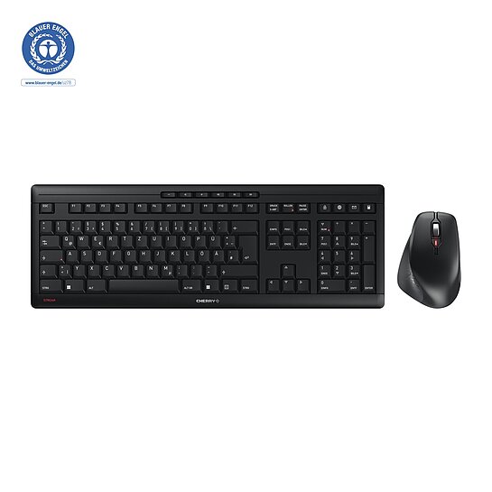
The wireless desktop set – Ergonomic and quiet working at its best

The silent click mouse with ergonomic shape and wireless freedom.
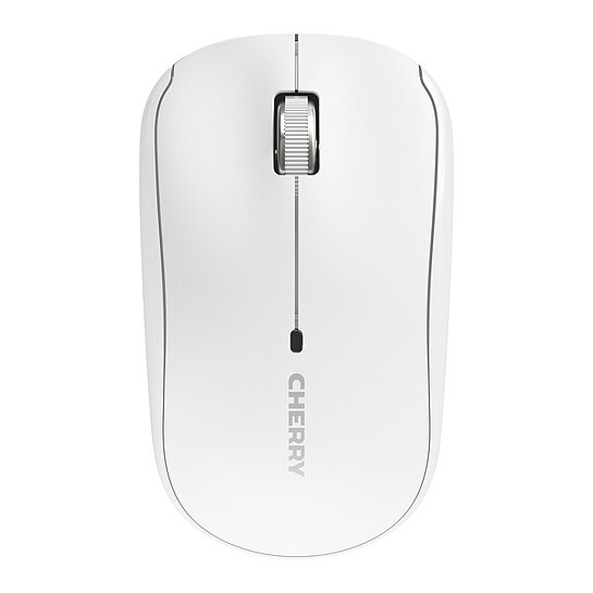
Compact Laptop Mouse with Nano USB Receiver and Carrying Case
Compact multi-device keyboard with Mac layout
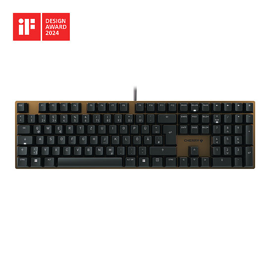
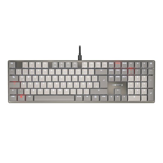
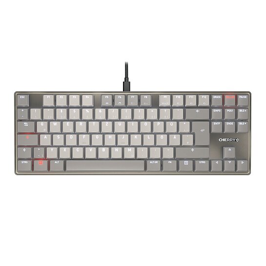
Minimalist Mechanical Keyboard with Anodized Aluminum Surface
Multi-Device Compact Keyboard with Three Bluetooth® Channels
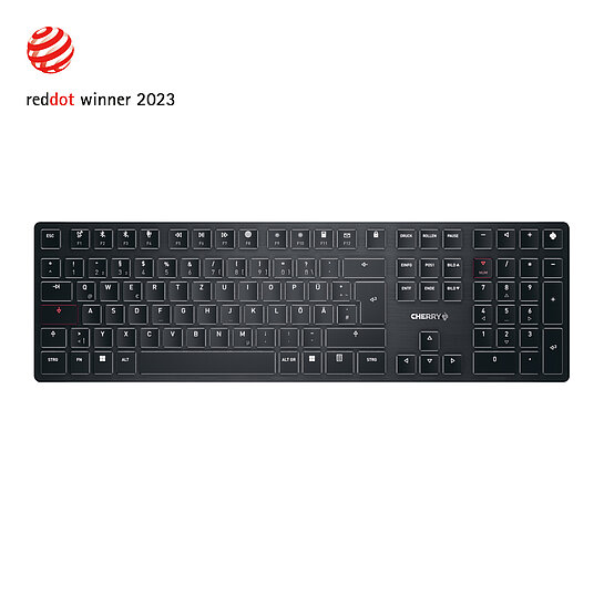
Ultra low profile high end keyboard with mechanical switches
Rechargeable multi-device compact keyboard with 2.4 GHz wireless, Bluetooth® 5.0 and cable connection
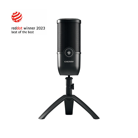
USB microphone for streaming and office use
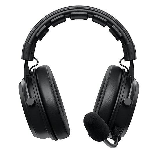
Wireless Pro Gaming Headset
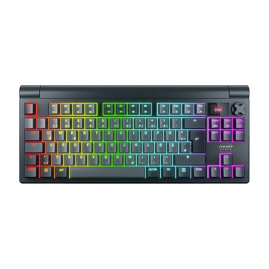
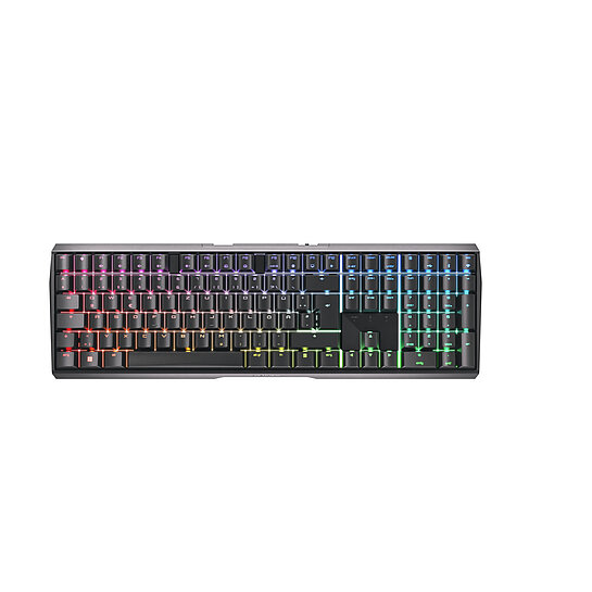
Mechanical gaming keyboard with LCD display
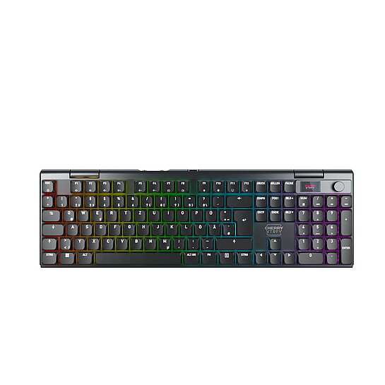
Mechanical low-profile gaming keyboard
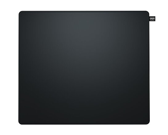
Gaming mouse pad made from graphene fabric
Cloth gaming mousepad
Mechanical gaming keyboard in TKL format
Next level gaming – powerful gaming keyboard in a trendy aluminum housing
Ultra-fast symmetrical gaming wireless mouse
Ultra-fast ergonomic gaming mouse
Professional USB & XLR mic for recording and streaming
Premium USB mic for recording and streaming
65% mechanical gaming keyboard
A colorful trendsetter: the small gaming keyboard for great performance at work too
Lightweight wired gaming mouse
The wireless gaming pro – a winner in both aesthetics and workmanship
Winning wireless speed – maximum wireless gaming performance in innovative aluminum design!
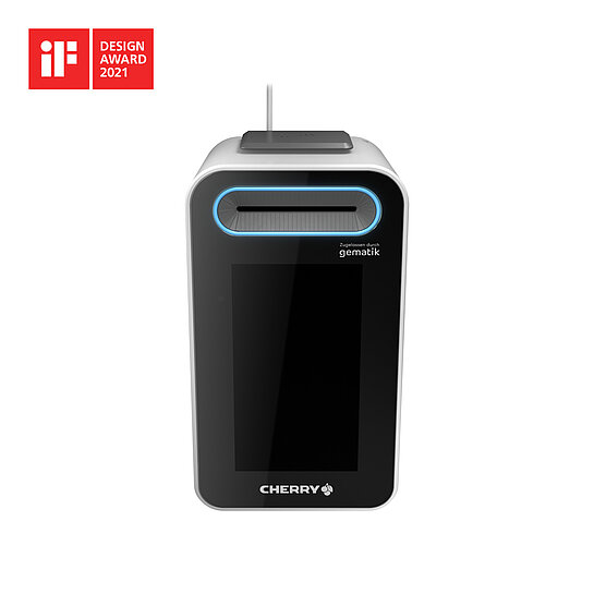
Easily disinfectable touchscreen solution for telematics infrastructure applications
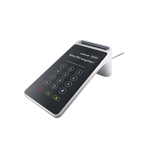
Easily disinfectable PIN-Pad for greater comfort and hygiene for patients and medical professionals
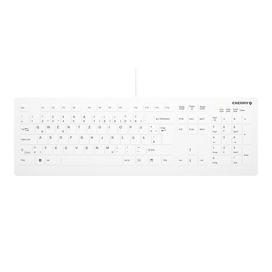
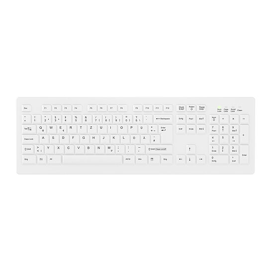
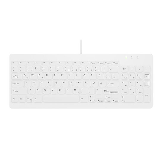
Disinfectable Medical Keyboard with full layout and flat key profile
Disinfectable wireless Medical Keyboard with full layout
Disinfectbale Medical Keyboard with numpad

Disinfectable Medical Keyboard with num pad
Disinfectbale Medical Keyboard with large touchpad
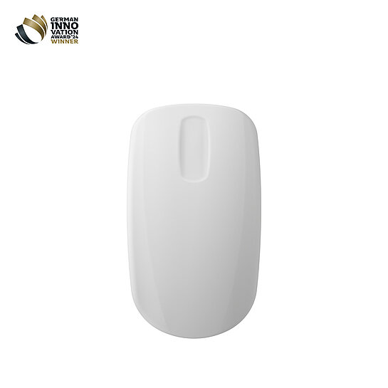
Wireless Medical Mouse with scroll sensor for glossy surfaces
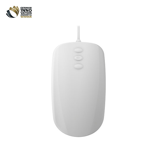
Medical Mouse with 3-button scroll for glossy surfaces
Fast and direct
Smooth and silent
Powerful and silent
Smooth and direct

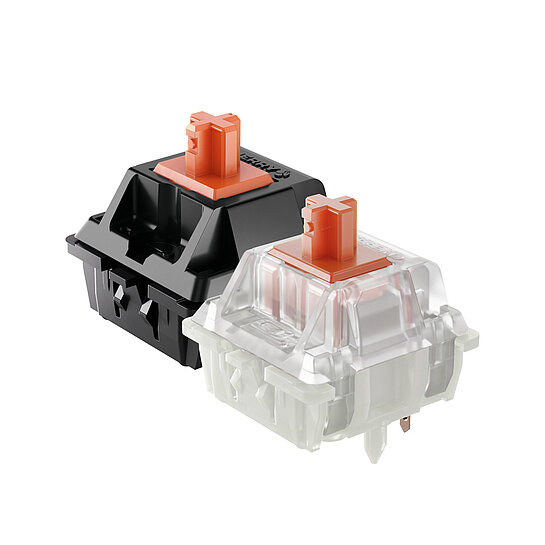
Focused and noticeable

Clicky and noticeable
Powerful and direct
Ultra-low profile, focused and noticeable
Ultra-low profile, clicky and noticeable
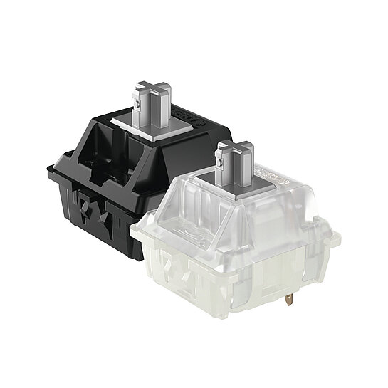
CHERRY MX SPEED SILVER - Fast and direct

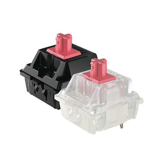
CHERRY MX SILENT RED - Smooth and silent
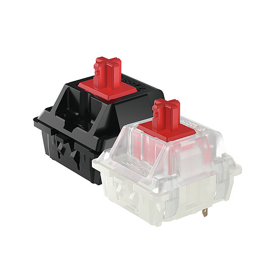
CHERRY MX RGB RED - Smooth and direct
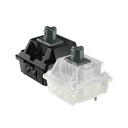
CHERRY MX GREY - Focused, robust and noticeable
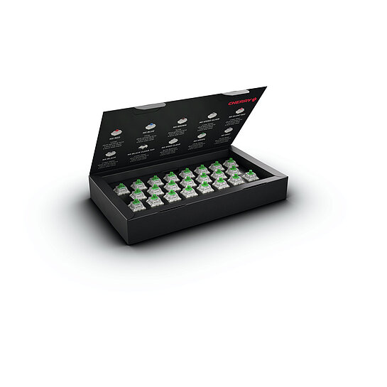
CHERRY MX GREEN - Clicky, robust and noticeable
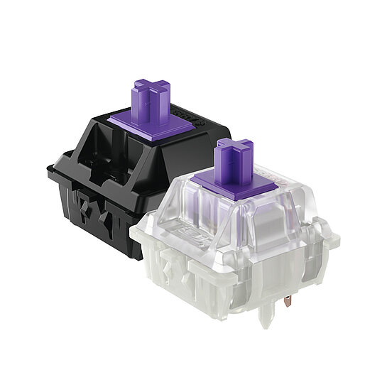
CHERRY MX ERGO CLEAR - Focused, smooth and noticeable
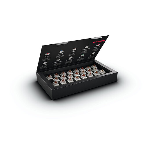
CHERRY MX BROWN - Focused and noticeable
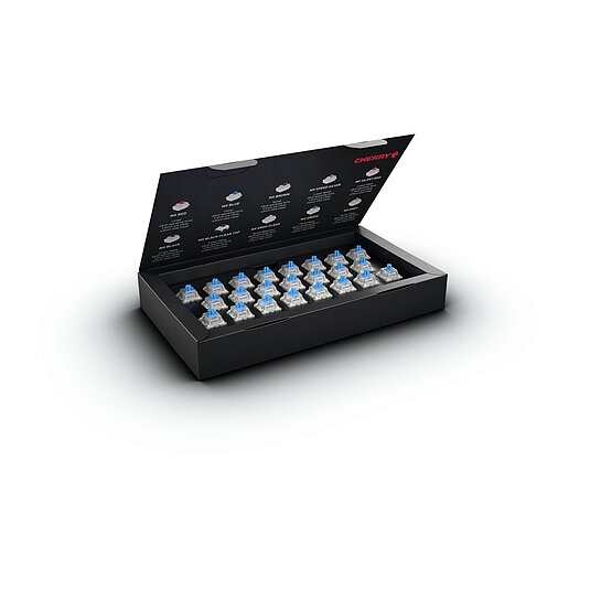
CHERRY MX BLUE - Clicky and noticeable
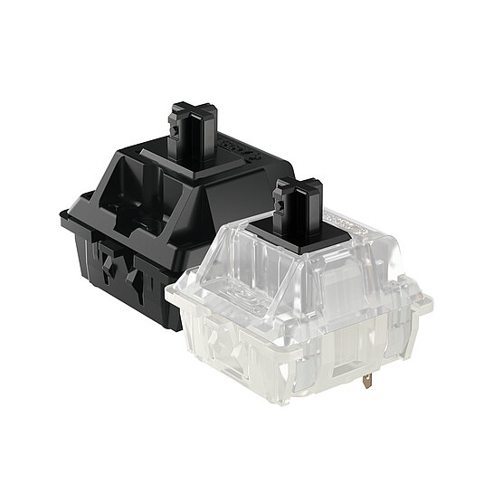
CHERRY MX BLACK - Powerful and direct
Reactive and tactile
The revival of a long-lost legend
Fast and inductive
Controllable and inductive
Powerful and inductive

Quicked-witted, fast and direct

Quick-witted, smooth and direct
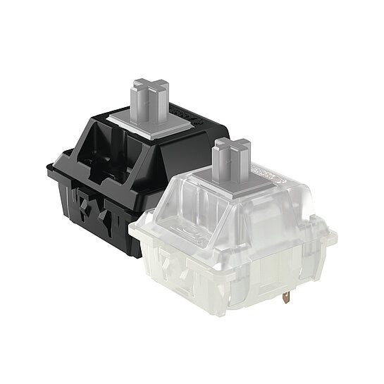
Focused, robust and noticeable
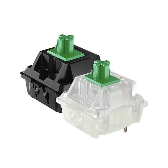
Clicky, robust and noticeable
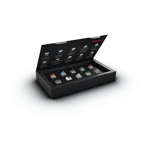
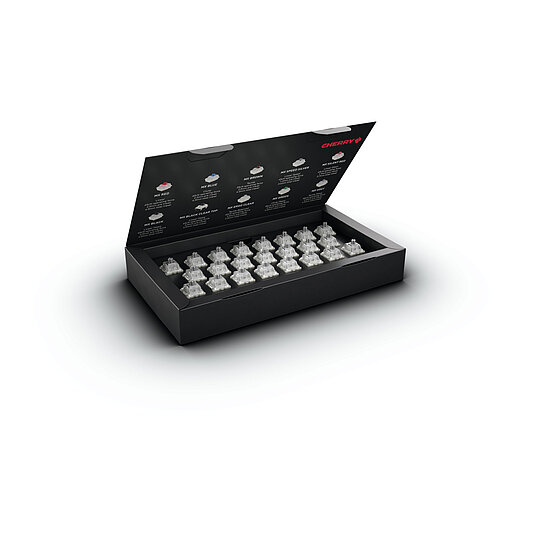
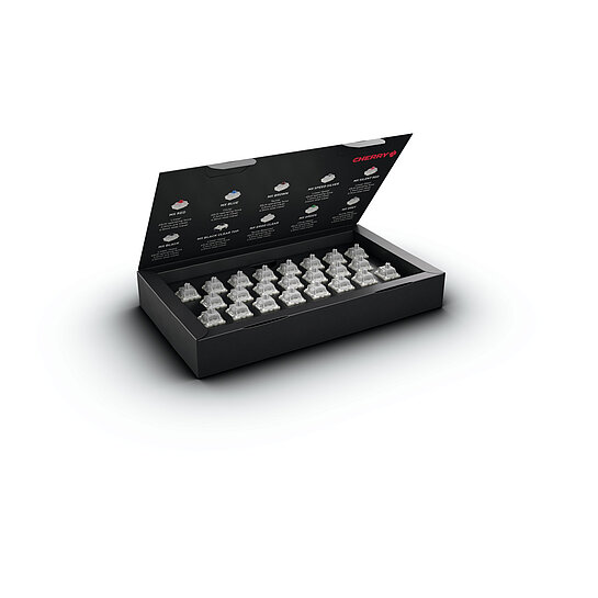
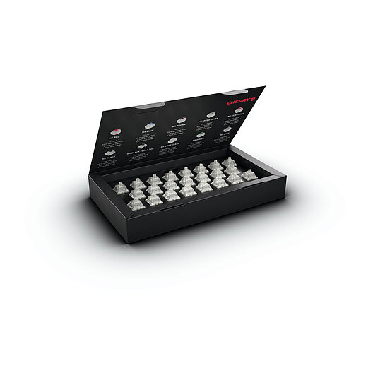
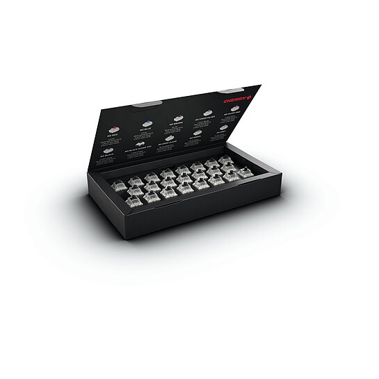
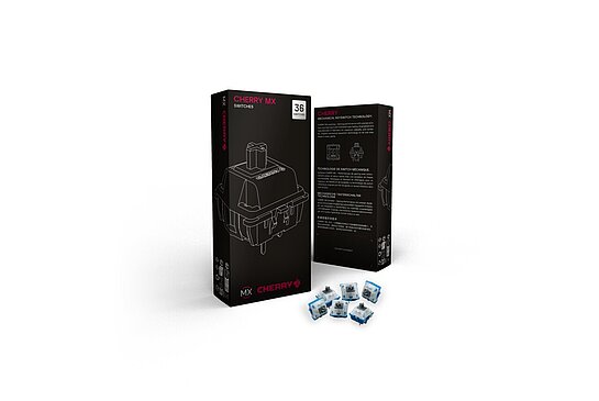
10 CHERRY MX switches in one box
Focused, powerful and noticeable
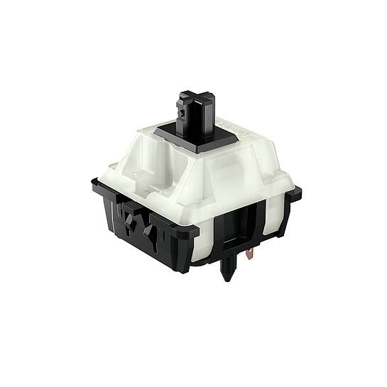
Powerful, direct and retro
CHERRY MX BLACK CLEAR TOP - Powerful, direct and retro
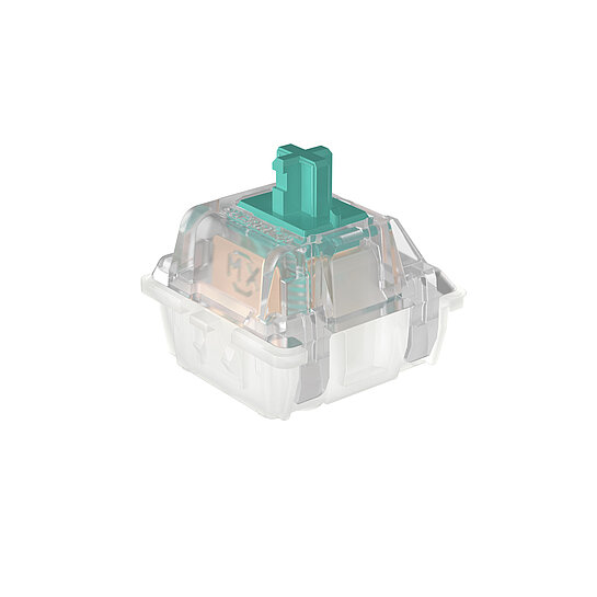
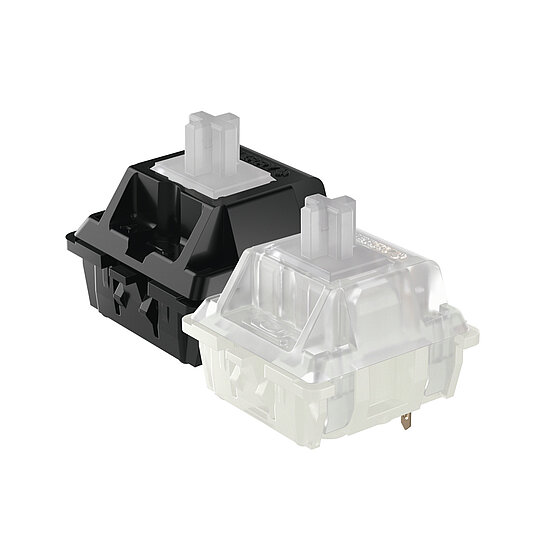
CHERRY MX NORTHERN LIGHT - Silent and Super-Smooth
Focused, smooth and noticeable
Ultra-Smooth and silent
Individual key assignment with CHERRY KEYS.
Do you have questions about our products or technologies? We will be happy to help you.
Become part of the CHERRY family and apply now for our current vacancies.
We are CHERRY!
Ambitious specialists dedicated to refining simple solutions, empowering individuals to reach their goals effortlessly. Bright solutions that set the standard for optimal input and output, both now and in the future. We are experts at transforming the ordinary into the extraordinary.
This outstanding ability is our legacy: A thrilling saga of American roots combined with precision and engineering made in Germany. From this combination grew an unstoppable, electrifying force – making us what CHERRY is today: An international powerhouse.
Continuously innovating, we craft tailored solutions for unparalleled quality, performance, and reliability. This is the original CHERRY spirit.
Enter Excellence with us!